
The Engine of Connection: A Deep Dive into Coaxial and RF Cable Manufacturing
In an invisible symphony of signals that powers our modern world, from a simple Wi-Fi connection to the most complex satellite communication, one component plays a fundamental role: the coaxial cable. As the largest manufacturer of coaxial and RF cables, we don’t just produce components; we engineer the vital pathways that carry information, entertainment, and critical data across the globe. This definitive guide pulls back the curtain on the sophisticated art and science of coaxial cable manufacturing. We will explore the intricate process from raw materials to finished product, detail the different types of cables, and illuminate their vast applications. Understanding this depth is crucial for anyone specifying, installing, or relying on robust communication systems.
In the fast-paced world of telecommunications, broadcasting, and wireless technology, coaxial and RF (Radio Frequency) cables play a pivotal role in delivering high-quality signal transmission. As the world’s largest manufacturer of coaxial and RF cables, we pride ourselves on producing innovative, reliable solutions that power everything from home internet to advanced military communications. But how are these essential cables made? What materials go into their construction? In this in-depth guide, we’ll explore the coaxial cable manufacturing process, the diverse types of coaxial and RF cables, their wide-ranging applications and uses, and the unbeatable benefits they offer. Whether you’re an engineer, installer, or business owner optimizing your network, this article provides the insights you need to understand why coaxial and RF cables remain indispensable in modern connectivity.
As the largest manufacturer of coaxial and RF cables, we take pride in producing high-performance cables that power critical industries worldwide. From telecommunications to aerospace, coaxial and RF cables are the backbone of seamless signal transmission. In this article, we’ll explore how these cables are manufactured, the materials used, different types of cables, and their applications and benefits.
Understanding Coaxial and RF Cables
Coaxial cables are electrical cables that carry high-frequency signals with minimal loss and interference. They consist of a central conductor surrounded by dielectric insulation, metallic shielding, and an outer jacket.
RF (Radio Frequency) cables are designed to transmit radio signals in a specific frequency range. Coaxial cables are the most common type of RF cables used in communication systems, data transmission, and broadcasting.
At their core, coaxial cables—often referred to simply as “coax”—are cylindrical electrical cables designed to transmit high-frequency signals with minimal loss and interference. They consist of a central conductor surrounded by a dielectric insulator, a metallic shield, and an outer jacket. RF cables are a specialized subset of coaxial cables optimized for radio frequency applications, handling signals from a few MHz up to several GHz.
These cables excel in environments where electromagnetic interference (EMI) is a concern, thanks to their unique structure that confines the signal within the cable. Unlike twisted-pair or fiber optic cables, coax provides a balanced impedance (typically 50 or 75 ohms) ideal for RF transmission. As global demand for 5G, IoT, and high-definition broadcasting surges, understanding their production is key to appreciating their reliability.
The Coaxial and RF Cable Manufacturing Process: Step by Step
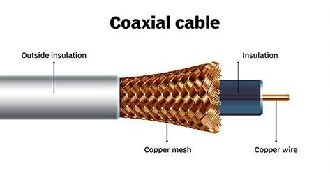
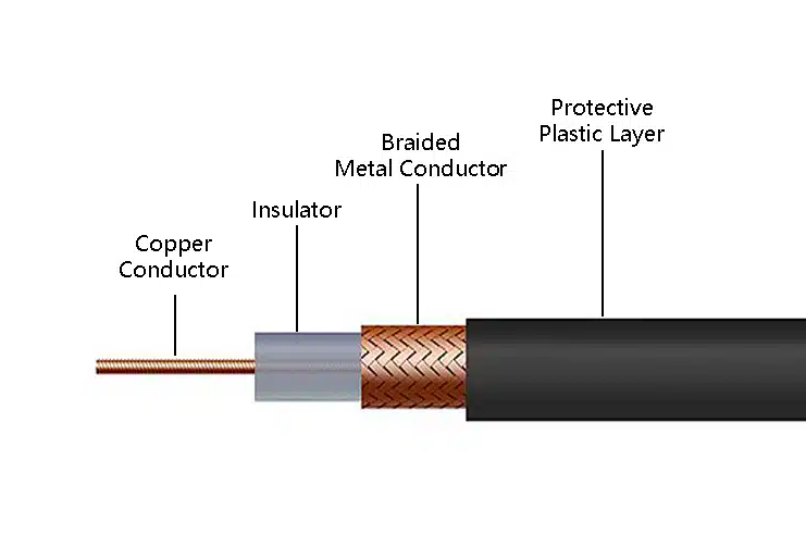
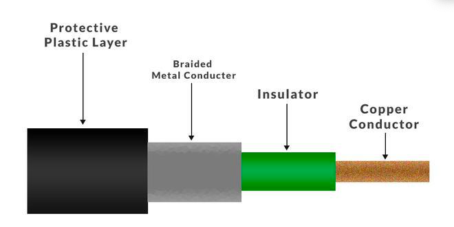
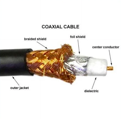
Before delving into how it’s made, it’s essential to understand what it’s made of. A coaxial cable is a masterpiece of layered engineering, with each component serving a critical purpose. The term “coaxial” itself refers to the fact that all these layers share a common geometric axis.
Center Conductor: At the heart of the cable lies the center conductor, typically made of bare copper, copper-clad steel (CCS), or silver-plated copper. This is the pathway for the electrical signal. Its size and material determine the cable’s flexibility and electrical conductivity.
Dielectric Insulation: Surrounding the center conductor is a layer of dielectric material, such as solid polyethylene, foam polyethylene, or PTFE (Teflon®). This insulator serves two key functions: it maintains a precise, consistent distance between the center conductor and the shield, and it defines the cable’s key electrical properties, most importantly its impedance (typically 50 or 75 ohms).
Shielding: This is the cable’s defense system. To protect the sensitive signal from external electromagnetic interference (EMI) and prevent the signal from leaking out, one or more shielding layers are applied. This can include:
Braid Shield: A woven mesh of thin metallic wires (often tinned copper) that provides flexibility and good overall protection.
Foil Shield: A thin aluminum foil laminated to a polyester film, offering 100% coverage against high-frequency interference.
High-performance cables often use multiple shields (e.g., double-shield or quad-shield) for maximum effectiveness.
Protective Jacket: The final layer is the jacket, made from materials like PVC, Polyethylene (PE), or Low-Smoke Zero-Halogen (LSZH) compounds. This jacket protects the internal components from moisture, abrasion, chemicals, and UV radiation, ensuring longevity in harsh environments.
| Component | Common Materials | Purpose and Benefits |
|---|---|---|
| Center Conductor | Bare copper (BC), Copper-Clad Steel (CCS), Silver-Plated Copper | High conductivity for signal transmission; CCS reduces cost without sacrificing performance. |
| Dielectric Insulator | Foam Polyethylene (PE), Solid PE, Teflon (PTFE) | Low dielectric constant (1.3-2.3) minimizes loss; foam variants enhance flexibility and velocity. |
| Shield/Braid | Tinned Copper Braid, Aluminum Foil, Beryllium Copper | >90 dB shielding rejects EMI/RFI; metallized polymers for lightweight RF applications. |
| Outer Jacket | PVC, FEP, Thermoplastic Elastomer (TPE) | Weatherproofing, UV resistance, and flame retardancy; FEP for high-temp RF environments up to 200°C. |
1. Conductor Preparation
The process begins with the center conductor, usually a solid or stranded copper wire (or copper-clad steel for cost efficiency). Raw copper rods are drawn through dies to achieve the desired gauge, then annealed for flexibility. For RF cables, purity is critical to minimize signal attenuation. It begins with large spools of copper rod. This rod is drawn through a series of progressively smaller dies to achieve the exact diameter required. For flexible cables, multiple thin copper strands are twisted together to form a stranded center conductor that can withstand repeated bending.
The process starts with high-purity copper (solid or stranded).
Copper undergoes annealing to improve conductivity and flexibility.
Surface treatment ensures smoothness and durability.
2. Dielectric Insulation Extrusion
The conductor is fed into an extruder where the dielectric material—often foam polyethylene (PE) or Teflon—is applied. This “foaming” process injects gas into the molten polymer to create a low-density insulator that reduces signal loss. High-frequency RF cables may use advanced Skin-Foam-Skin techniques for RG-6 or RG-11 types, ensuring uniform thickness and air pockets for optimal velocity of propagation (around 80-85%).
The center conductor is fed into an extrusion crosshead. Here, molten dielectric material is applied uniformly around the conductor. This is a critical stage; the temperature, pressure, and cooling rates must be meticulously controlled. Any inconsistency, like an air bubble, will alter the dielectric constant, leading to an unstable impedance and increased signal loss. For low-loss cables, the dielectric is “foamed,” introducing tiny air bubbles to lower the dielectric constant and improve performance.
A dielectric layer (usually polyethylene, PTFE, or foam PE) is extruded over the conductor.
This layer maintains consistent spacing, which is critical for impedance control.
Advanced foaming techniques help reduce signal loss.
3. Shielding Application – The Art of Protection
Foil Shielding: A tape of aluminum foil is precisely wrapped around the dielectric in a longitudinal direction.
Braid Shielding: High-speed braiding machines, equipped with multiple carrier spools, weave a precise mesh of metallic strands over the core. The braid density (e.g., 60%, 95%) is a key factor in the shield’s effectiveness. Advanced cables may go through multiple braiding stations.
4. Outer Jacket Extrusion
The final layer, the protective jacket, is extruded over the shielded core. Materials like PVC, polyethylene, or fluorinated ethylene propylene (FEP) are melted and applied evenly. This step includes UV stabilizers for outdoor use and flame-retardant additives for safety compliance.
The shielded core is run through a final extruder where the protective outer jacket is applied. The choice of jacket material—flexible PVC for indoor use, rugged UV-resistant PE for outdoor applications, or safety-focused LSZH for plenums and public spaces—is determined by the cable’s end-use environment.
A protective jacket is added using PVC, PE, LSZH (Low Smoke Zero Halogen), or Teflon.
Provides resistance against moisture, UV rays, oil, chemicals, and physical stress.
5. Testing and Quality Assurance – Our Uncompromising Standard
Connectors (e.g., BNC, SMA) are crimped or soldered onto ends for assemblies. Rigorous testing follows: spark testers check for dielectric defects, capacitance meters verify impedance, and attenuation sweeps ensure low loss up to 6 GHz. Thermal cycling stabilizes the cable for harsh environments. Finally, the cable is spooled, labeled, and packaged.
This multi-stage process, often automated with machines like those from Winton or Maillefer, guarantees cables meet MIL-SPEC and RoHS standards. Innovations like micro-coaxial assembly lines allow for miniaturized RF cables in compact devices.
Time-Domain Reflectometry (TDR): This sends a pulse down the cable to check for imperfections and ensure impedance uniformity along the entire length.
Return Loss/VSWR Testing: Measures the efficiency of the cable by quantifying how much signal is reflected back to the source.
Attenuation Testing: Verifies that the signal loss over frequency meets the strict specifications.
Impedance accuracy
VSWR (Voltage Standing Wave Ratio)
Mechanical strength and flexibility
Applications and Uses of Coaxial and RF Cables
Coaxial and RF cables are the backbone of signal transmission across industries. The unique structure of coaxial cable provides benefits that make it the preferred choice for countless critical applications.
Telecommunications: The backbone of 4G/LTE and 5G networks, connecting cell towers to antennas.
Broadcasting & Media: Transmitting high-definition audio/video signals for television and satellite broadcasting.
Data Networking: Used in cable internet (DOCSIS) infrastructure.
- Wireless and RF Systems: Antenna-to-transmitter links in 4G/5G towers, GPS, and radar.
Military & Aerospace: Ruggedized cables for radar, avionics, and communication systems where failure is not an option.
Medical Technology: Ensuring signal clarity in MRI machines and patient monitoring equipment.
Industrial IoT & SCADA: Connecting sensors and antennas in automation and control systems.
- Audio and Instrumentation: Pro audio setups, test labs for precise signal integrity.
Consumer Electronics – Home entertainment, gaming, and antenna connections.
Benefits of High-Quality Coaxial and RF Cables
- Superior Shielding and Low Interference: Braided/foil designs block EMI, enabling longer runs (up to 100m) with minimal signal degradation.
- Low Attenuation and High Bandwidth: Foam dielectrics support frequencies up to 6 GHz, ideal for HD video and data.
- Durability and Flexibility: Rugged jackets withstand weather, bending (bend radius as low as 1 inch), and temperatures, reducing maintenance.
- Cost-Effective Reliability: Cheaper than fiber for short-to-medium distances; easy installation with standard connectors.
- Versatility: Scalable from micro to hard-line for diverse power levels (up to 10 kW peak).
Superior Shielding: Excellent protection against electromagnetic interference (EMI).
High Bandwidth: Capable of carrying high-frequency signals with large amounts of data.
Controlled Impedance: Maintains signal integrity over long distances.
Durability: Built to withstand mechanical stress and environmental challenges.
Types of RG and RF Cables
Now that we understand the step by step process to manufacture the cable, components involved with manufacturing the cable and the benefits and applications, we must learn about the different types of cables and their uses.
The term “RG” (Radio Guide) was originally used by the military to designate coaxial cables. Today, RG cables are widely used in telecommunications, broadcasting, internet, CCTV, defense, and electronics. Each RG cable type differs in impedance, diameter, shielding, and frequency handling, making them suitable for different applications.
The RG series has been the backbone of radio frequency (RF) and video connectivity for decades. While newer, low-loss alternatives exist, RG cables remain immensely popular due to their standardization, cost-effectiveness, and wide availability. As the largest manufacturer of coaxial cables, we have an unparalleled depth of knowledge about this foundational product line.
This guide provides a complete reference to the most common RG coaxial cables, detailing their specifications, benefits, and ideal use cases. We will also present a clear comparison table to help you quickly select the right cable for your application.
The RG (Radio Guide) series represents one of the most established families of coaxial cables, originally developed for military applications but now ubiquitous in telecommunications, broadcasting, RF systems, and more. These cables are defined by MIL-SPEC standards (e.g., MIL-C-17), ensuring consistent performance in impedance, shielding, and signal integrity. While there are hundreds of RG variants, this guide focuses on the most common and widely used types, drawing from industry standards and manufacturer data. For each, we’ll cover key specifications, benefits and advantages, and applications. At the end, a comprehensive comparison table highlights differences to help you select the right cable.
RG cables excel in high-frequency signal transmission due to their balanced construction: a central conductor, dielectric insulator, metallic shield, and protective jacket. They offer excellent EMI/RFI rejection and are cost-effective for runs up to several hundred feet.
Common RG Series Coaxial Cables
1. RG-6
Impedance: 75 Ω
Diameter: ~6.9 mm
Frequency Range: Up to 3 GHz
Uses & Applications:
Cable TV and satellite connections
CCTV surveillance systems
Broadband internet
Home theater systems
2. RG-11
Impedance: 75 Ω
Diameter: ~10.3 mm (thicker than RG-6)
Frequency Range: Up to 3 GHz
Uses & Applications:
Long-distance signal transmission
Underground TV and internet cable
Satellite & broadcasting networks
3. RG-59
Impedance: 75 Ω
Diameter: ~6.1 mm
Frequency Range: Up to 1 GHz
Uses & Applications:
Analog CCTV systems
Older cable TV installations
Short-run video/audio connections
Not ideal for high-speed internet
4. RG-58
Impedance: 50 Ω
Diameter: ~5 mm
Frequency Range: Up to 1 GHz
Uses & Applications:
Two-way radio communication
Ham radios & CB radios
Low-power signal transmission
Networking (legacy 10BASE2 Ethernet)
5. RG-213
Impedance: 50 Ω
Diameter: ~10.3 mm
Frequency Range: Up to 1 GHz
Uses & Applications:
Military and defense communication
High-frequency radio transmission
Amateur (ham) radio antennas
Outdoor RF applications (UV-resistant jacket)
6. RG-174
Impedance: 50 Ω
Diameter: ~2.8 mm (very thin & flexible)
Frequency Range: Up to 1 GHz
Uses & Applications:
Internal wiring for electronic devices
GPS antennas
Short RF connections in compact equipment
Portable communication devices
7. RG-316
Impedance: 50 Ω
Diameter: ~2.5 mm
Frequency Range: Up to 3 GHz
Uses & Applications:
High-frequency military & aerospace systems
Test equipment connections
RF & microwave applications
Suitable for high-temperature environments (Teflon jacket)
8. RG-8
Impedance: 50 Ω
Diameter: ~10.3 mm
Frequency Range: Up to 1 GHz
Uses & Applications:
CB radios and ham radios
High-power RF transmission
Long-distance radio frequency links
Alternative to RG-213 in some cases
9. RG-214
Impedance: 50 Ω
Diameter: ~10.8 mm
Frequency Range: Up to 1 GHz
Uses & Applications:
Military-grade communication
High-power broadcast systems
Radar & satellite ground stations
Double-shielded for maximum EMI protection
10. RG-174 vs RG-178 vs RG-188 (Miniature Coax)
Impedance: 50 Ω
Diameter: ~1.8–2.8 mm
Frequency Range: 1–3 GHz (depending on type)
Uses & Applications:
Internal RF connections in electronics
Wi-Fi antennas & GPS modules
Compact test and lab equipment
Aerospace & military instrumentation
RG Coaxial Cable Comparison Table
| Cable Type | Impedance | Diameter (mm) | Max Frequency | Key Advantages | Typical Applications |
|---|---|---|---|---|---|
| RG-6 | 75 Ω | 6.9 | 3 GHz | Low loss, versatile | TV, Broadband, CCTV |
| RG-11 | 75 Ω | 10.3 | 3 GHz | Best for long runs | CATV backbone, Satellite |
| RG-59 | 75 Ω | 6.1 | 1 GHz | Flexible, low-cost | CCTV, Analog TV |
| RG-58 | 50 Ω | 5.0 | 1 GHz | Flexible RF cable | Radios, Lab RF tests |
| RG-213 | 50 Ω | 10.3 | 1 GHz | High power, outdoor use | Military, Ham Radio |
| RG-8 | 50 Ω | 10.3 | 1 GHz | Low attenuation | CB/Ham Radios, Base stations |
| RG-214 | 50 Ω | 10.8 | 1 GHz | Double shielded, EMI resistant | Military, Radar, Aerospace |
| RG-174 | 50 Ω | 2.8 | 1 GHz | Miniature, flexible | GPS, Wi-Fi, Portable devices |
| RG-316 | 50 Ω | 2.5 | 3 GHz | High-temp Teflon jacket | Aerospace, Microwave links |
| RG-178/188 | 50 Ω | ~2.0 | 3 GHz | Ultra-thin, lightweight | Avionics, Satellite equipment |
Important Considerations When Choosing an RG Cable
-
Impedance Matching is Critical: Always match the cable’s impedance (50Ω or 75Ω) to the impedance of your equipment. A mismatch will cause signal reflections, leading to poor performance and potential equipment damage.
-
Signal Loss (Attenuation): Thinner cables (like RG-174) have much higher signal loss than thicker cables (like RG-11). Choose a cable with low attenuation for long runs or high-frequency applications.
-
Flexibility vs. Durability: Stranded center conductors and more braids increase flexibility. Solid conductors and thicker jackets increase durability for outdoor or rugged use.
-
Jacket Material: Use PVC for general indoor use, PE for outdoor burial/direct sunlight, and LSZH for plenum spaces in buildings where fire safety is a concern.
Final Thoughts
The RG series coaxial cables cover a wide range of needs — from low-cost CCTV (RG-59) to high-performance aerospace applications (RG-316, RG-214).
-
50 Ω RG cables → best for RF, radio, military, and test equipment.
-
75 Ω RG cables → ideal for TV, video, CCTV, and broadband internet.
 As the largest coaxial and RF cable manufacturer, we supply the entire RG range with customizable jacketing, shielding, and lengths to meet industry-specific demands.